
The Link Layer aka Physical Layer
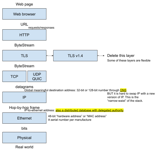
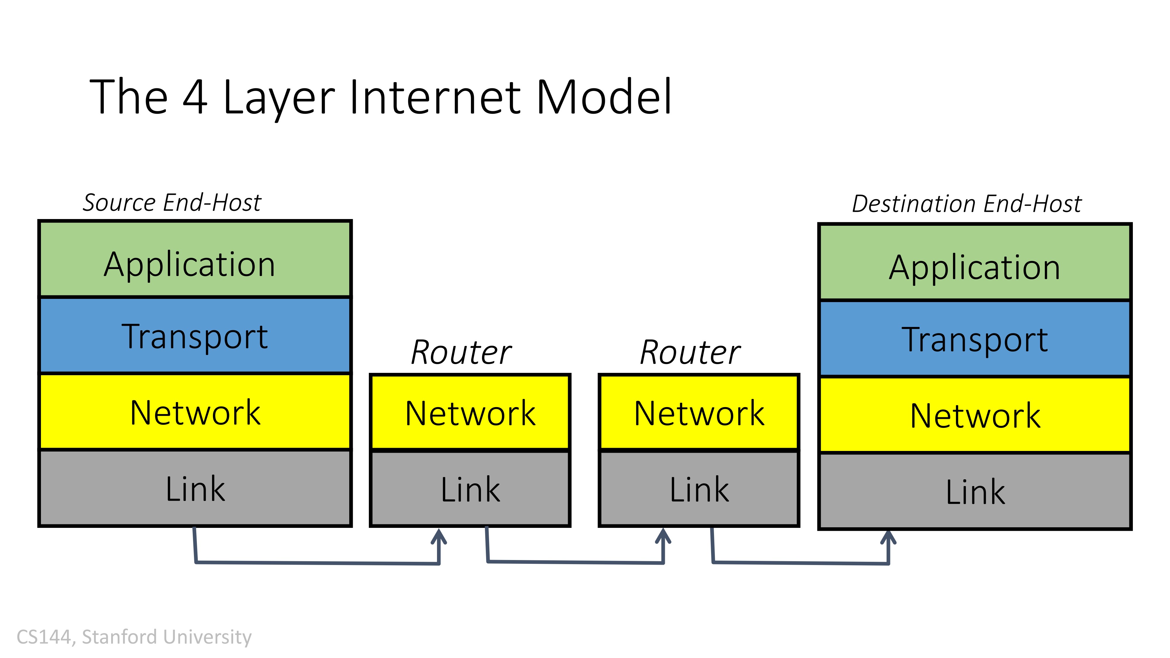
“OSI model” (4/5/7 layers)
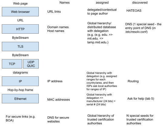
Last Time: How naming works? (How names are assigned and discovered?)
Q: Why can’t we use MAC address as our IP address?
A: we need a structured way to delegate the responsibility of “looking for the next hop given the IP address”. Using IP addresses make this easier, since each hop can only care about the prefix of IP addresses in the local routing table. However, if we are using unstructured addresses such as hardware addresses, the routing table would each of size the number of total hardware addresses.
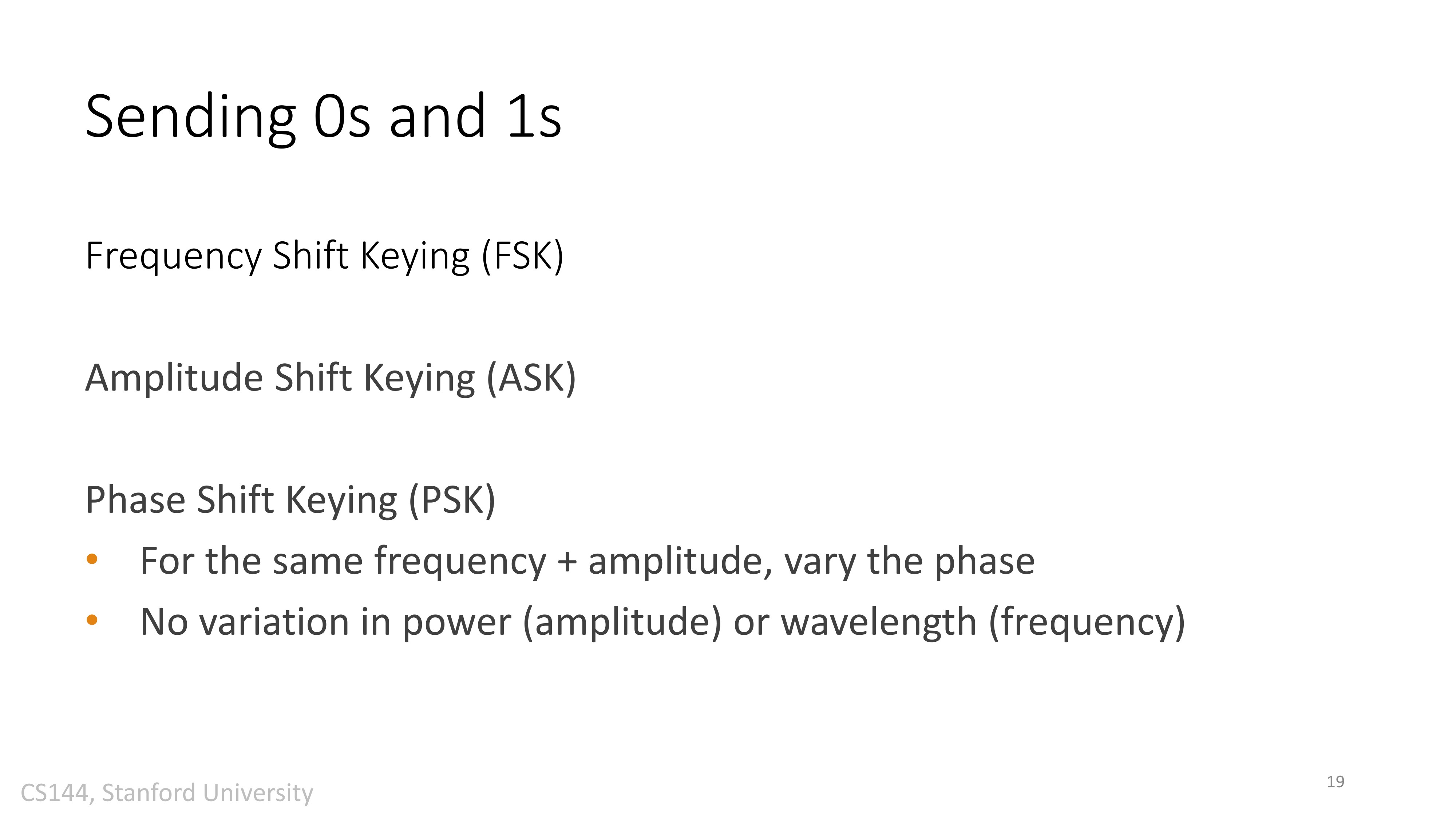
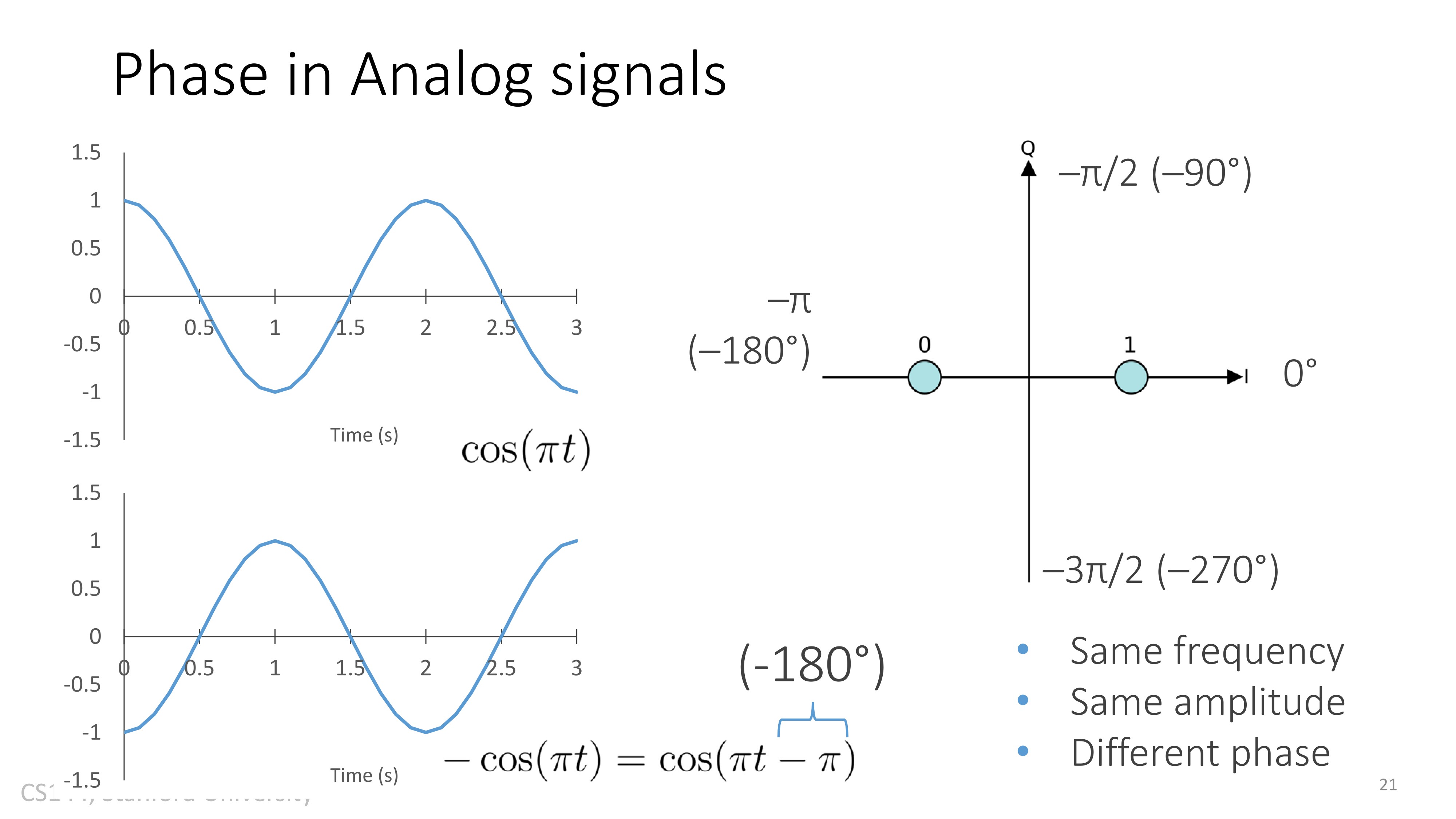
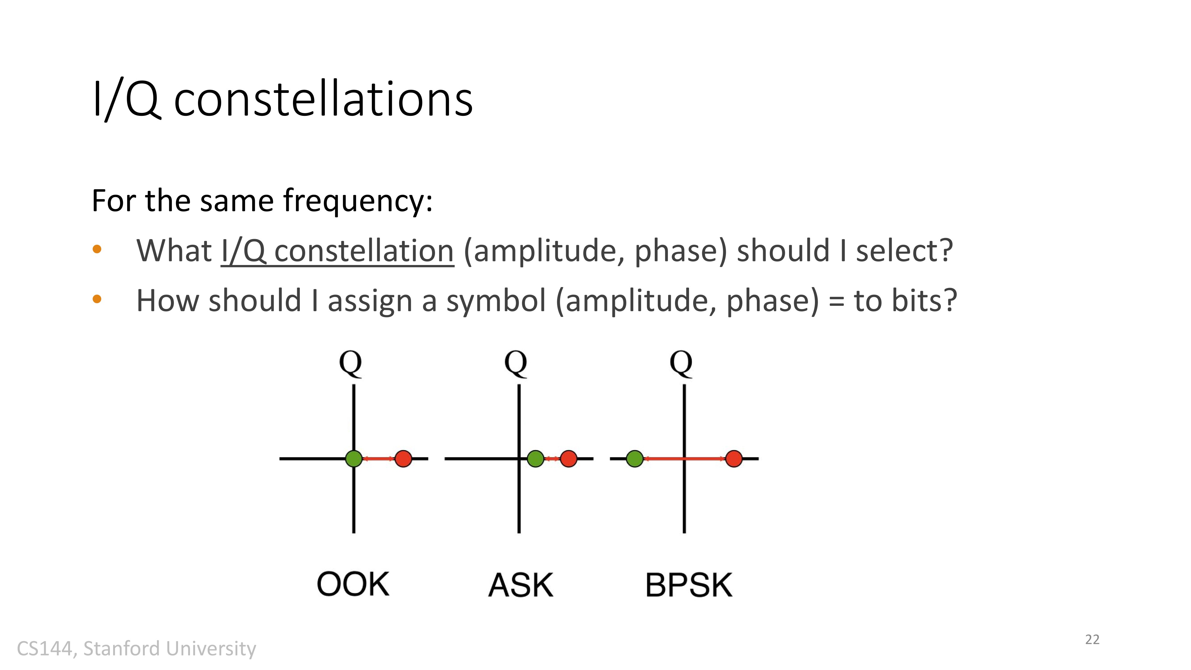
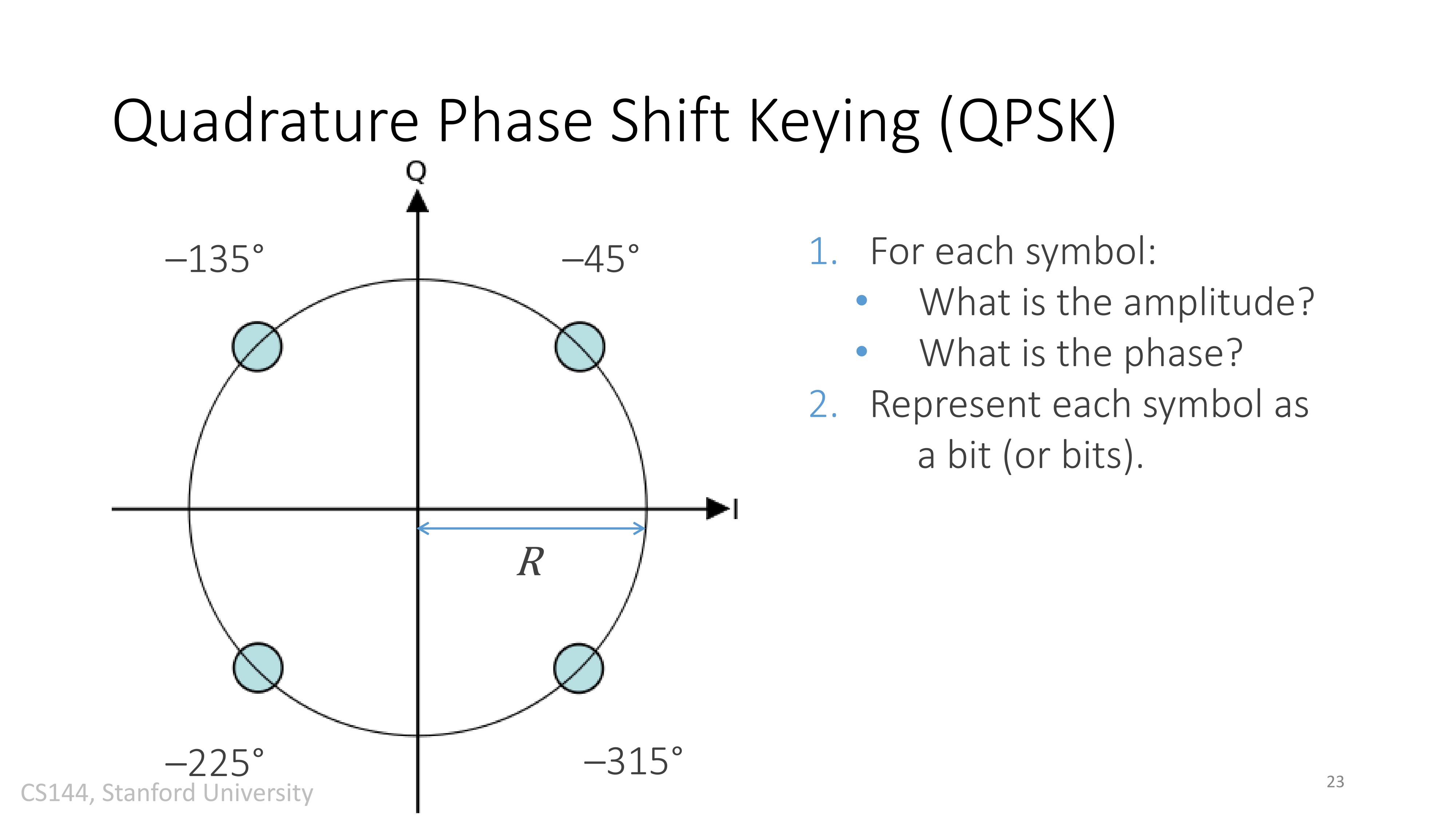
From “bits” to real world:
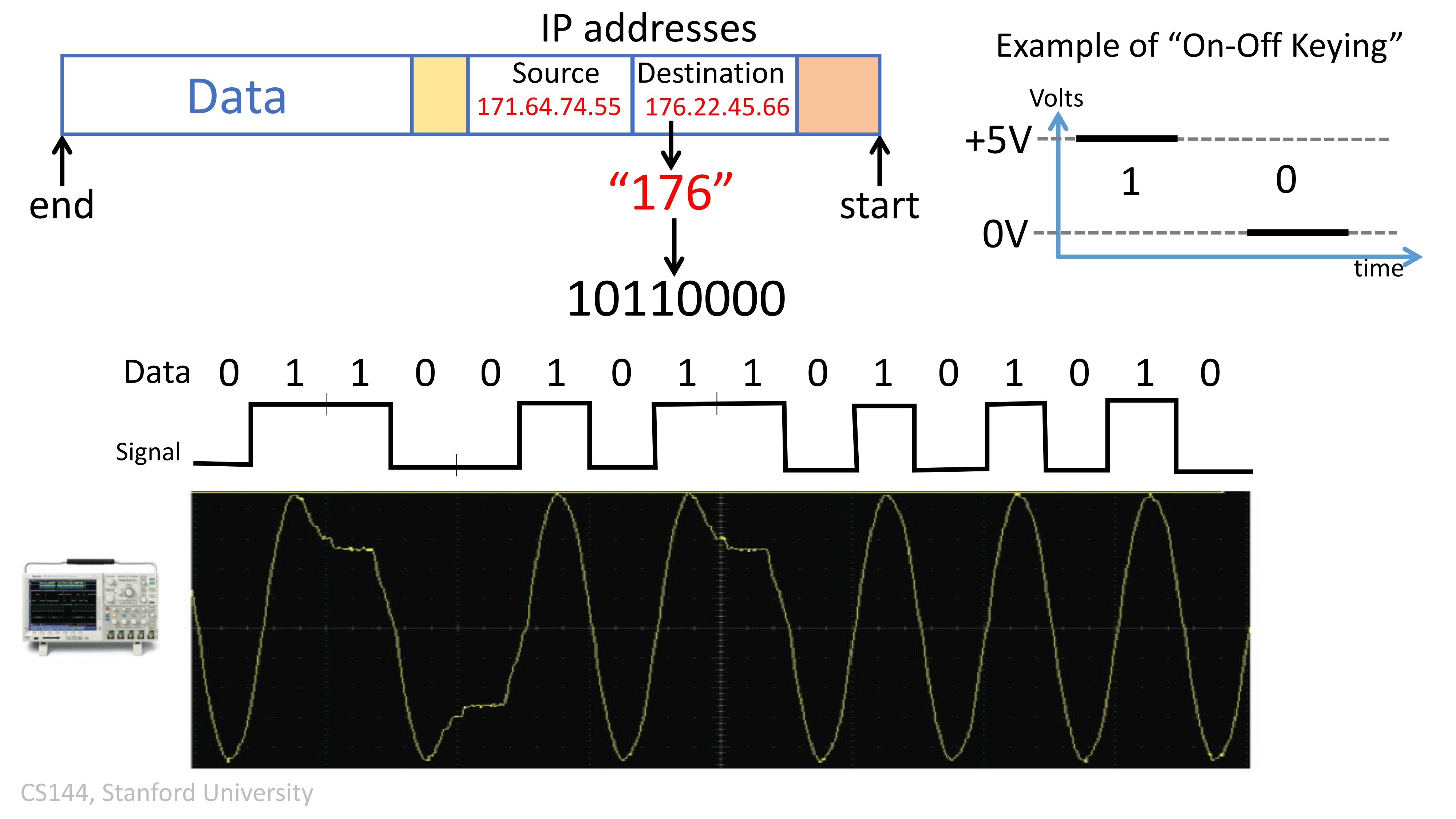
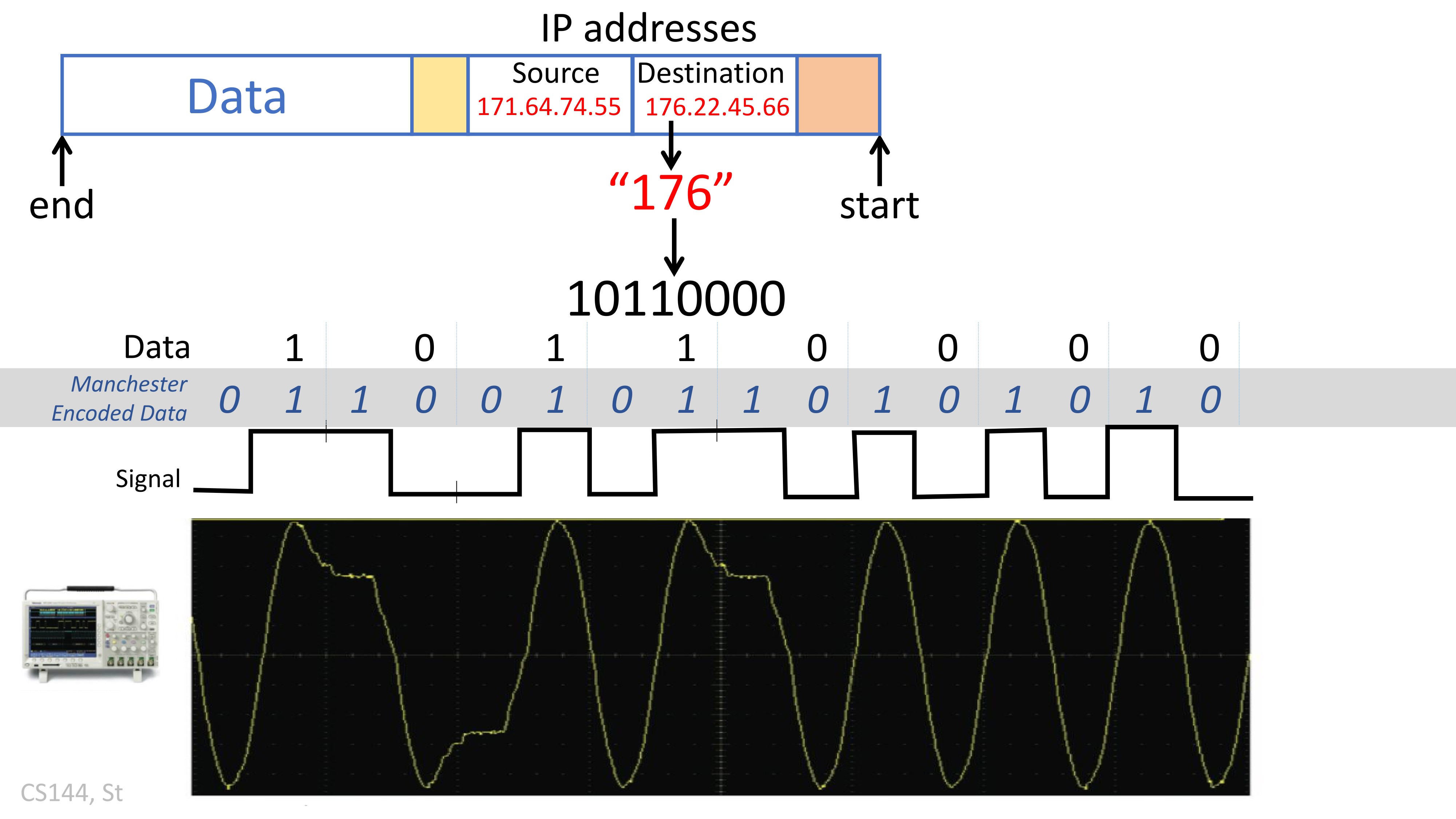
Bits are 0s and 1s: 10110110. How to translate that to analog.
One proposal: “1” -> high voltage/signal; “0” -> low voltage/signal
- The signal may be: low, high for a while, low for a while
- Then it’s hard to tell from the signal how many 0s and 1s there are without knowing how long each 0 and 1 lasts.
Another proposal: preamble - a special sequence before the actual stream to give the clock speed.
- preamble :
10101010- high low high low … - And then the receiver knows how long each “tick” is
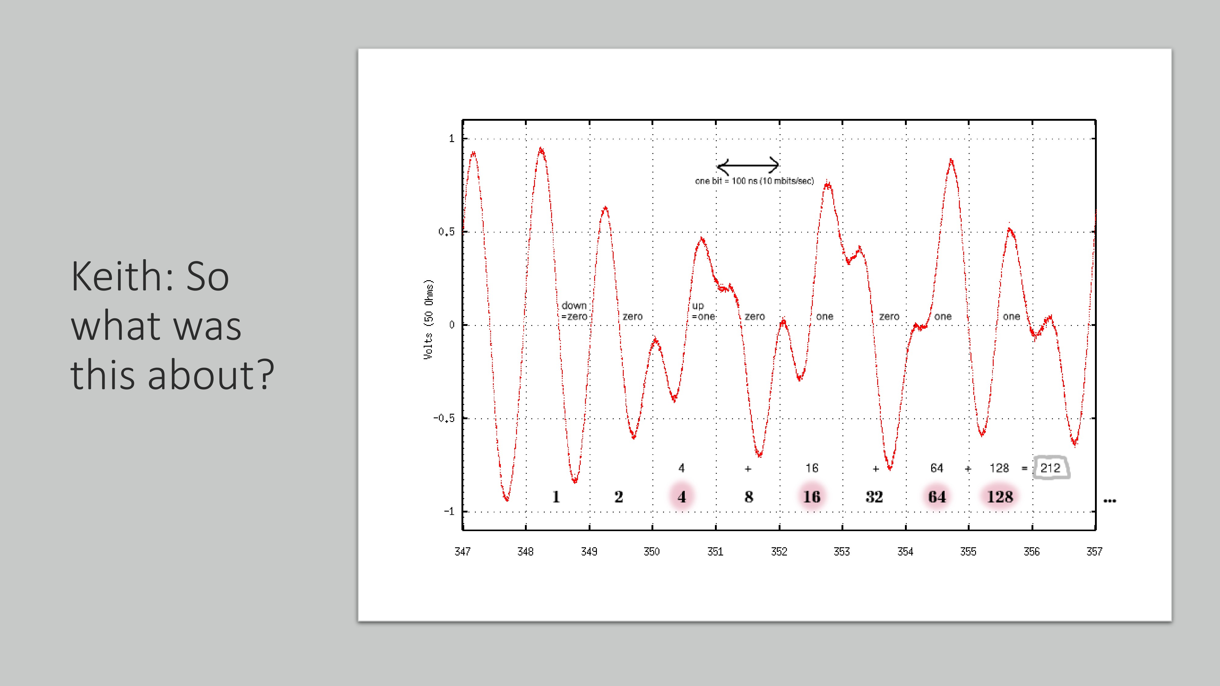
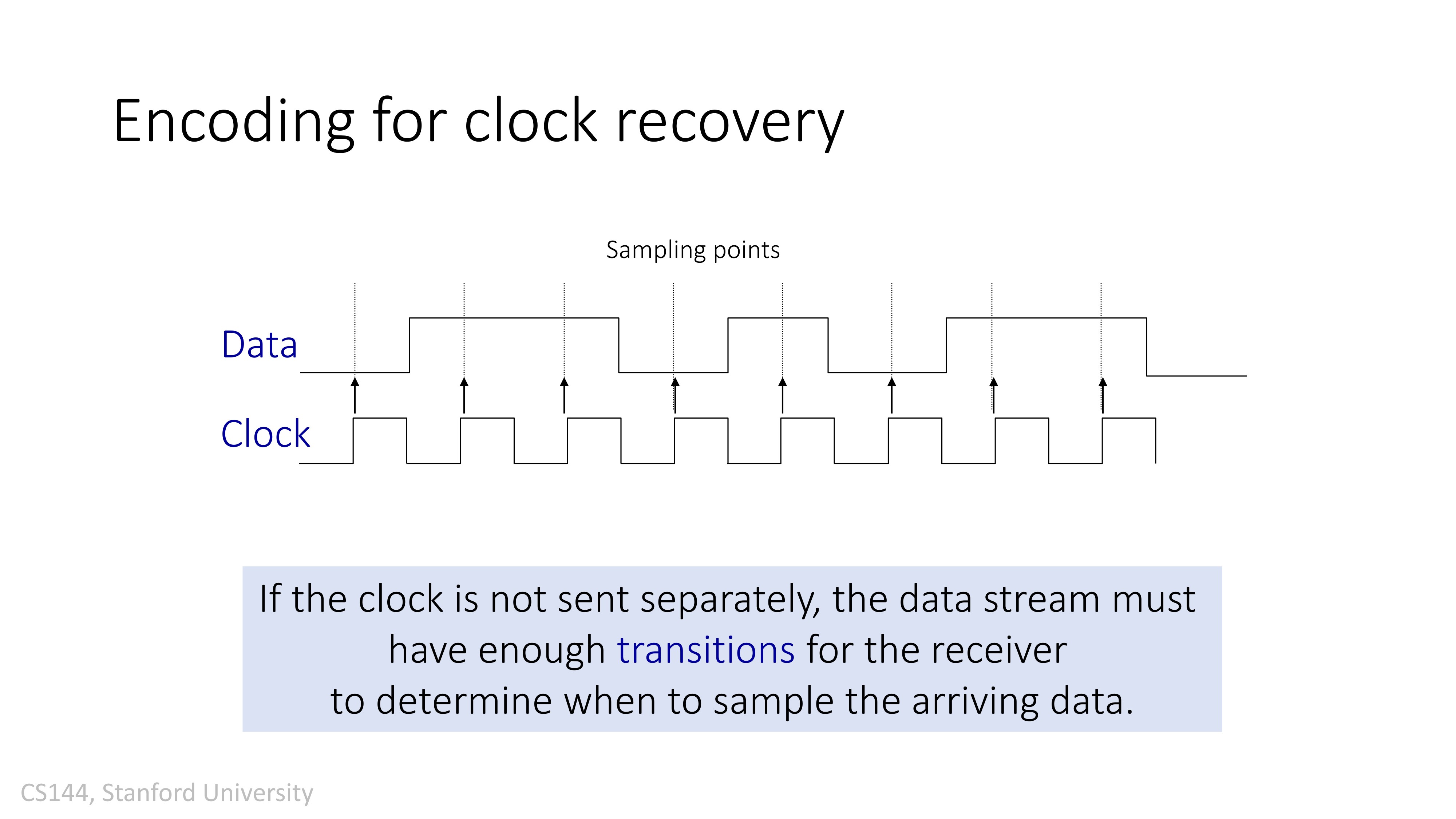
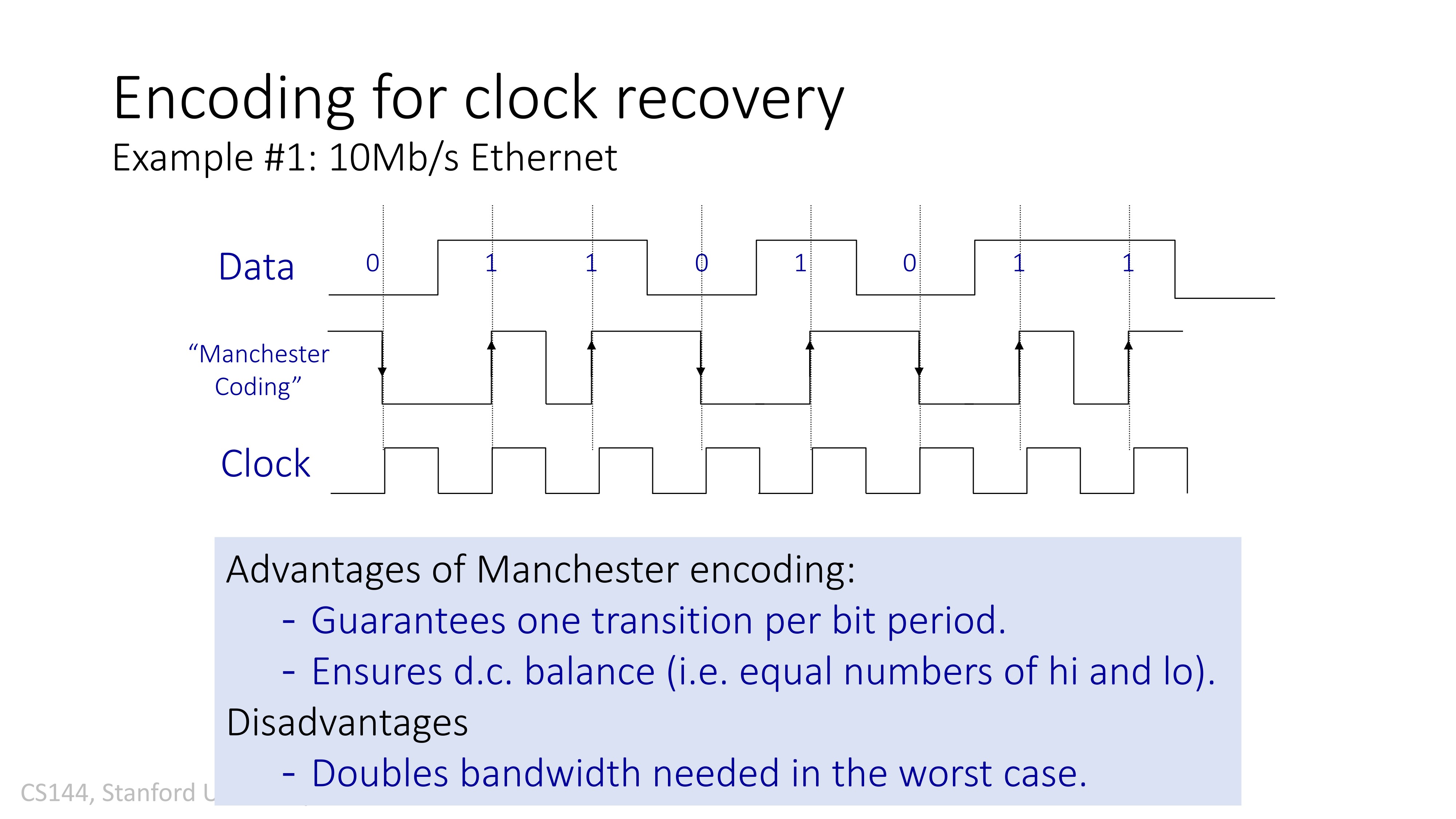
But preamble is not enough for clock synchronization. “0” -> downward transition, “1” -> upward transition.
- For each “clock tick”, there must be a transition.
- Therefore, the clock rate can be calculated by looking at the time interval between two transitions, whether each of them is downward or upward.
Shannon’s capacity
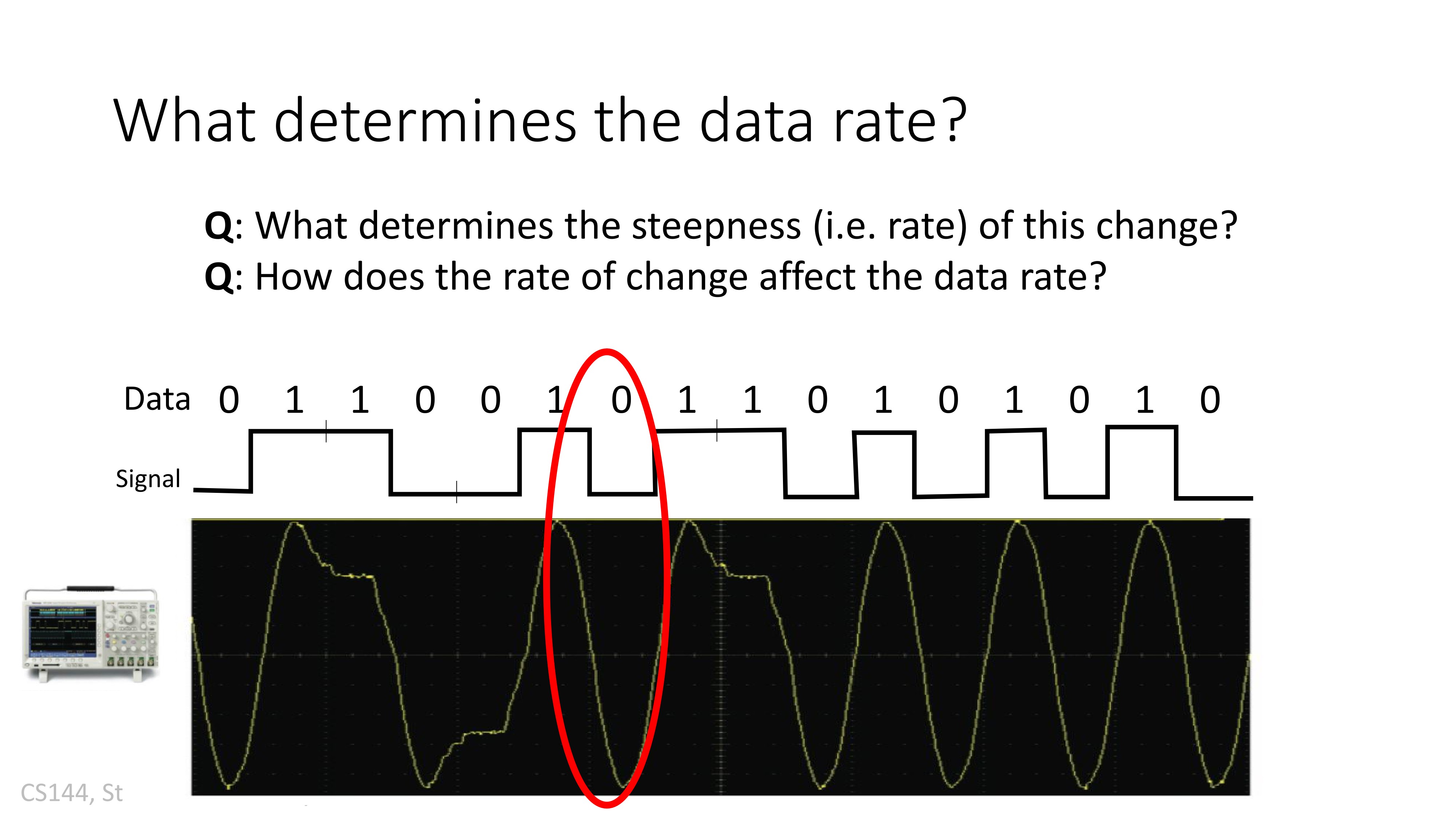
How did we tell what the link rate is?
Limits:
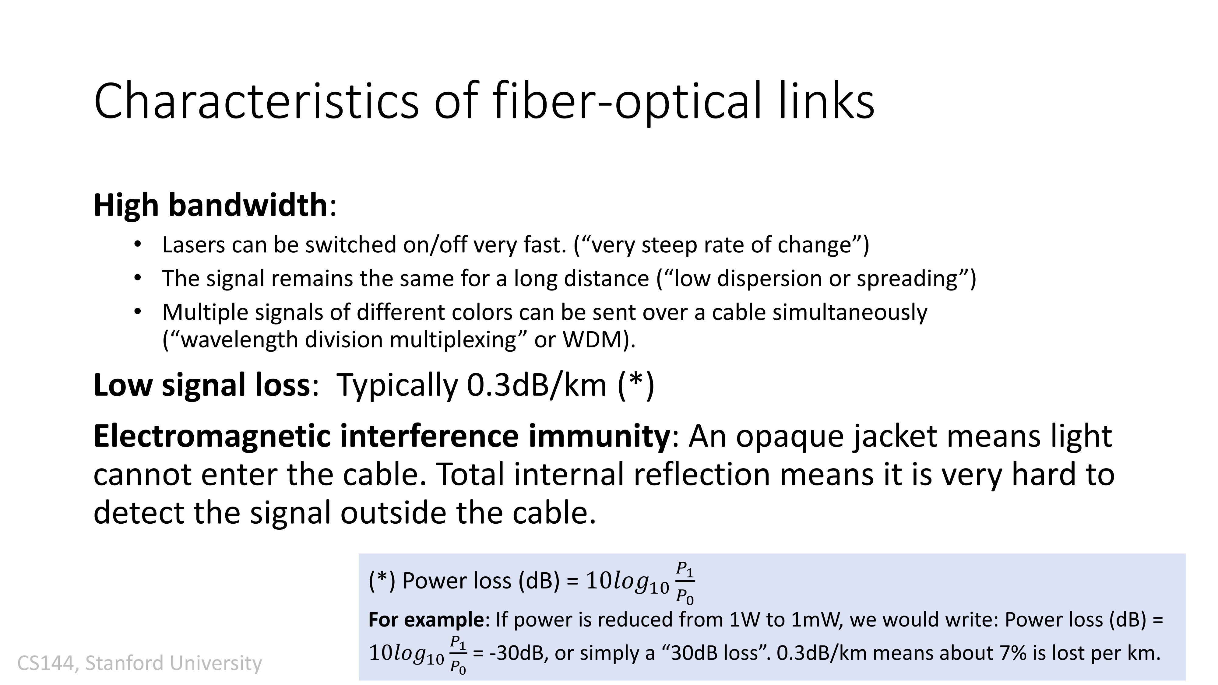
- Sender’s average power (“loudness”): more power probably means more bits per second
- Receiver’s average noise power: the larger the noise the less bits per second (assumes normal distribution)
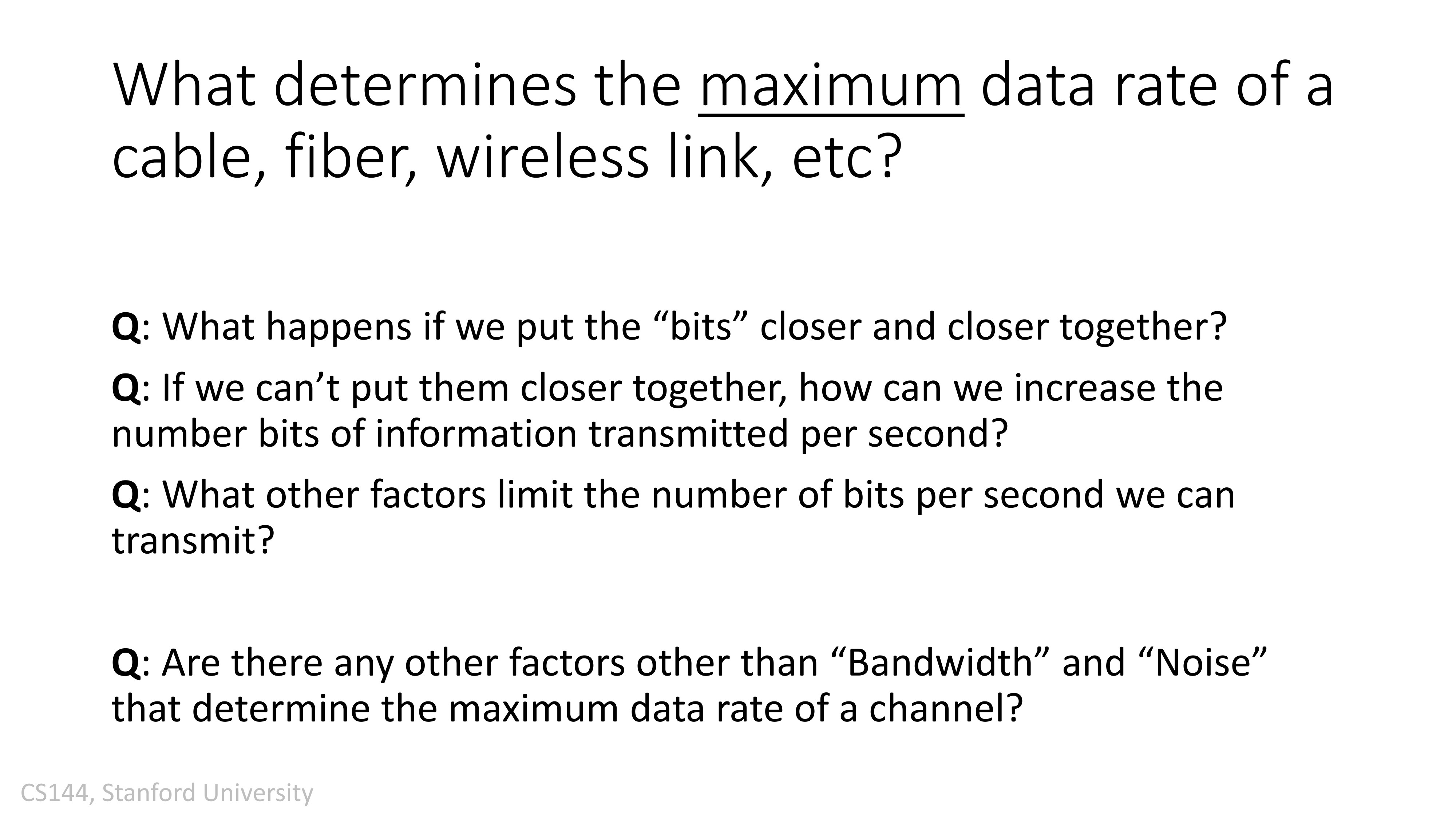
The band width - the range of frequencies allowed to use: the larger this range is the more can be transmitted
In the old days: people “believed” there were a tradeoff between link rate and error rate, and this can’t be precisely described in a mathematical way:
- Intuitively, the slower you send, the more power you put into each bits and then the message would be “clearer”
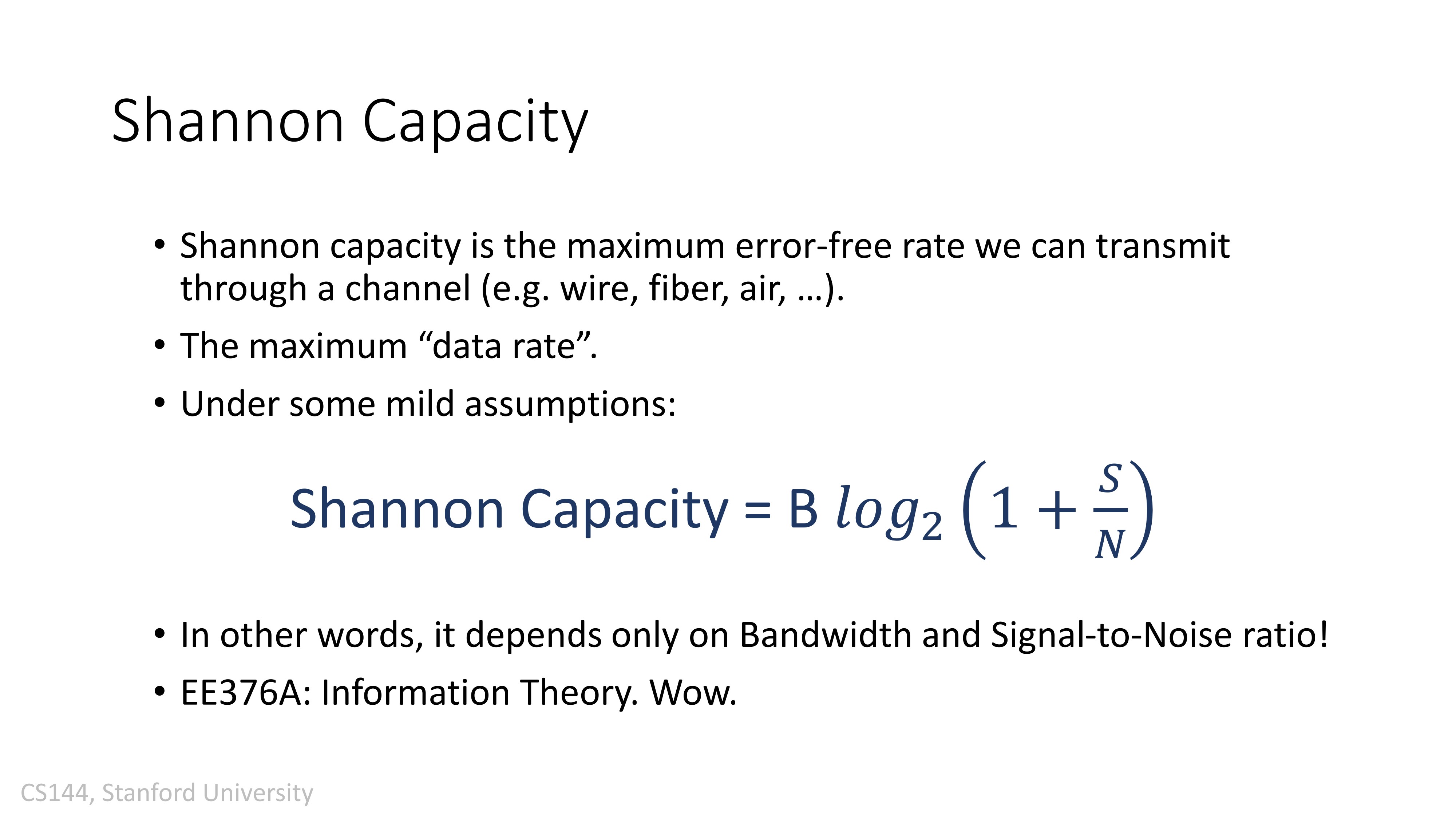
BUT, there is an equation:
[公式]
- (P - average power, N - average noise, W - band width)
- Single-flow from a sender to a receiver. If you send lower than the capacity C, for whatever error rate, it can be done period.
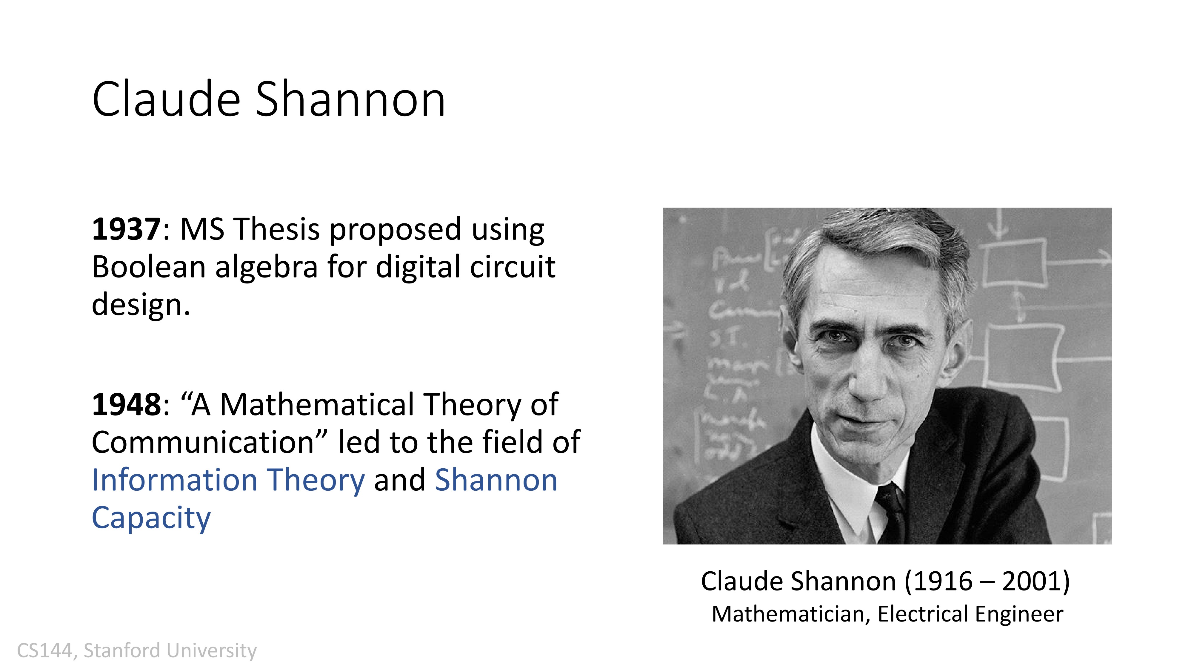
- Information theory (1948)
Bandwidth在模拟信号中可以指:
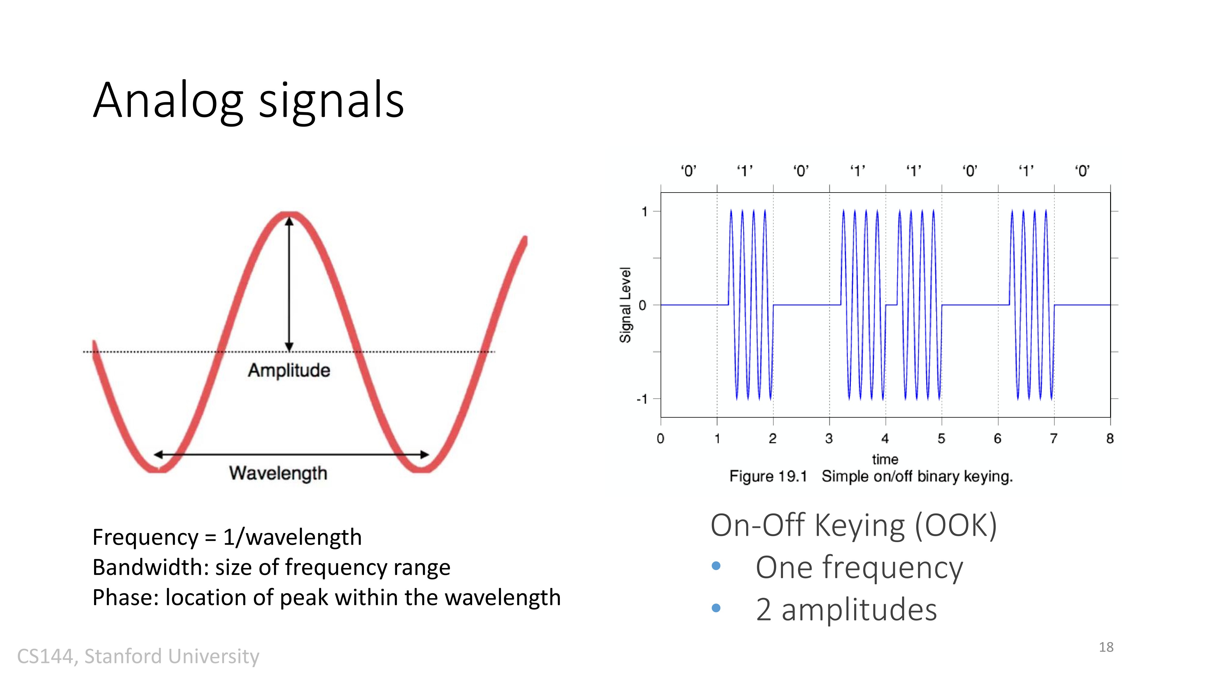
- 每秒周期数,即频率,以赫兹表示
- 信号所包含的不同频率成分所占据的频率范围。

Clock Synchronization
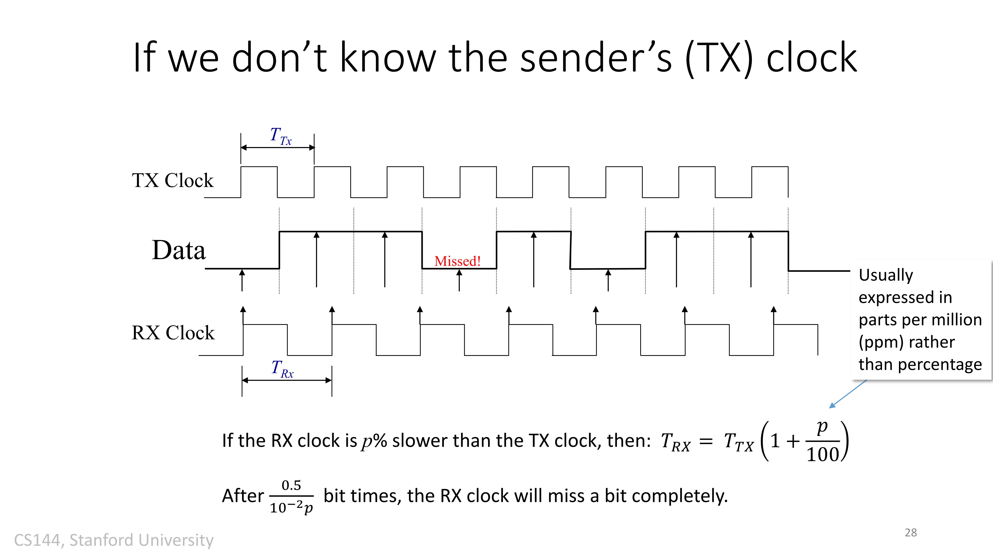
part per million(ppm):百万分之分数。比百分数更精确。
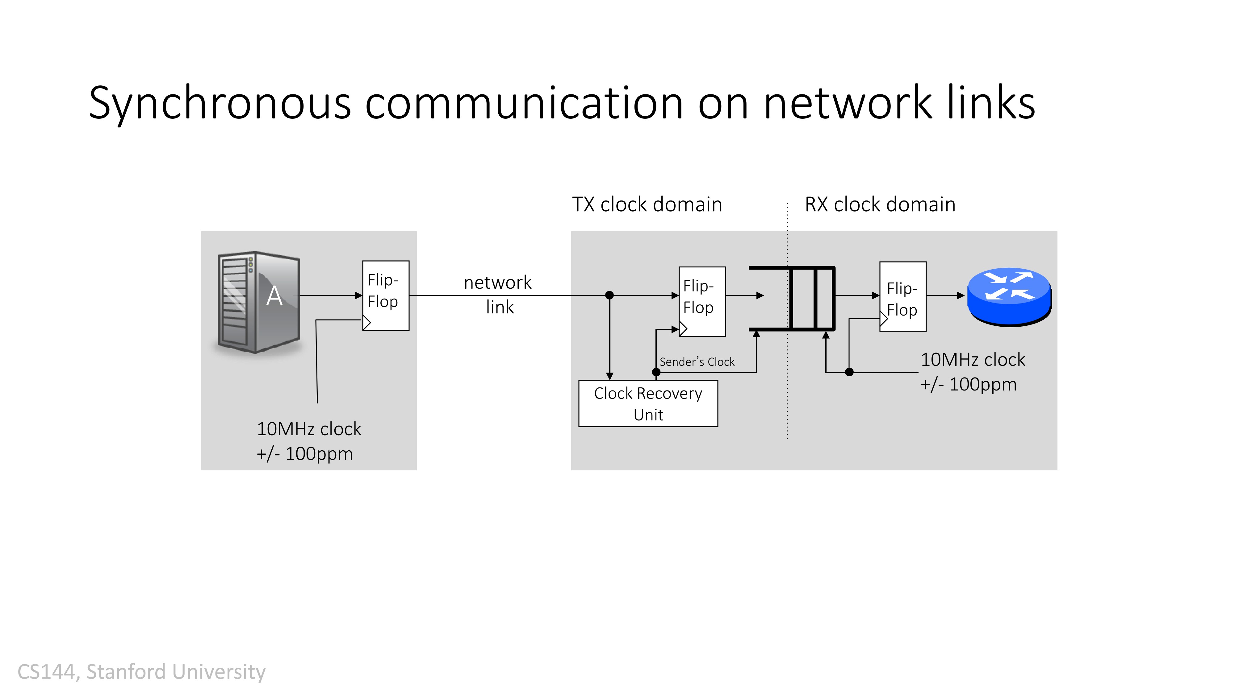
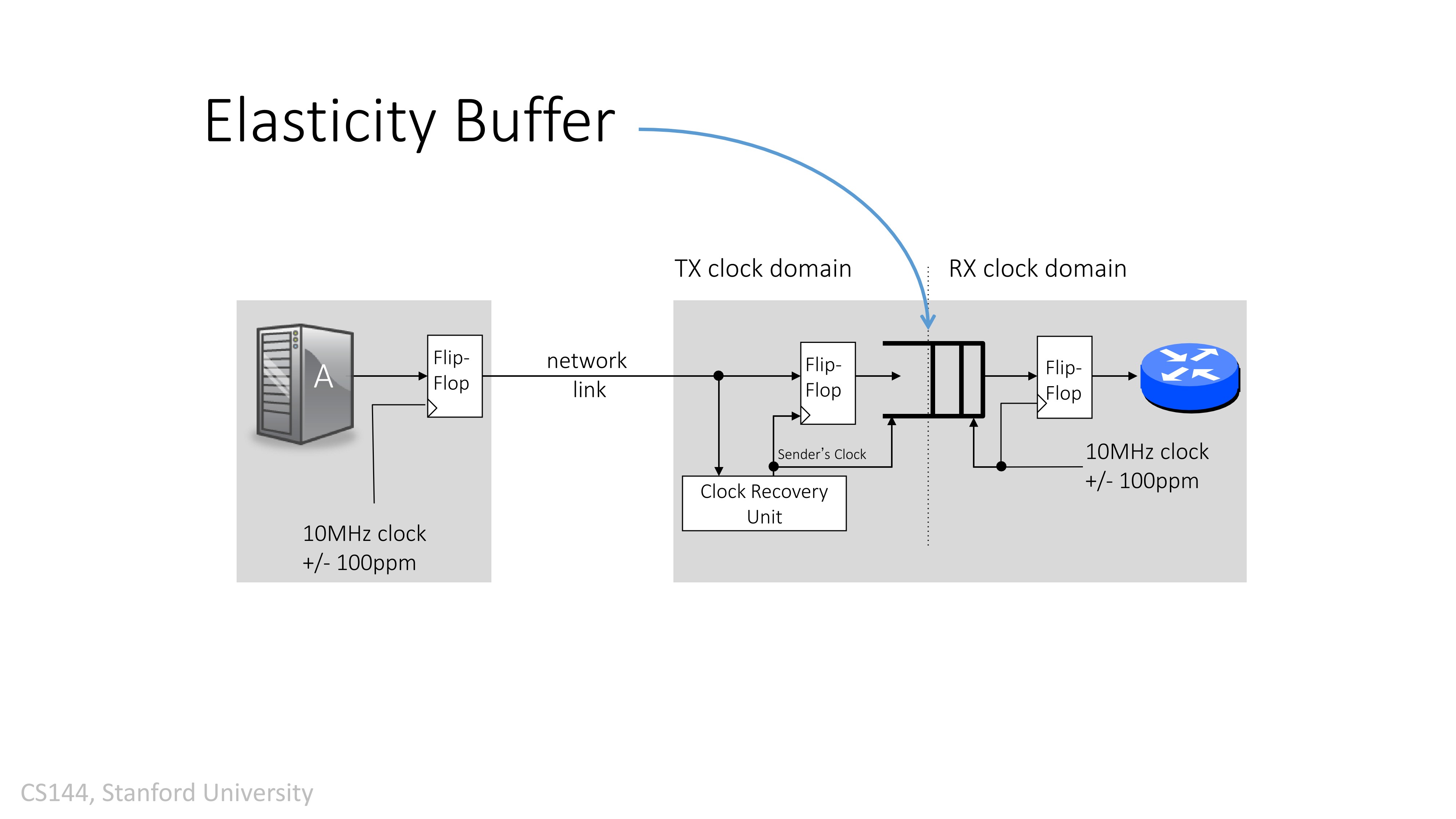
Elasiticity Buffer
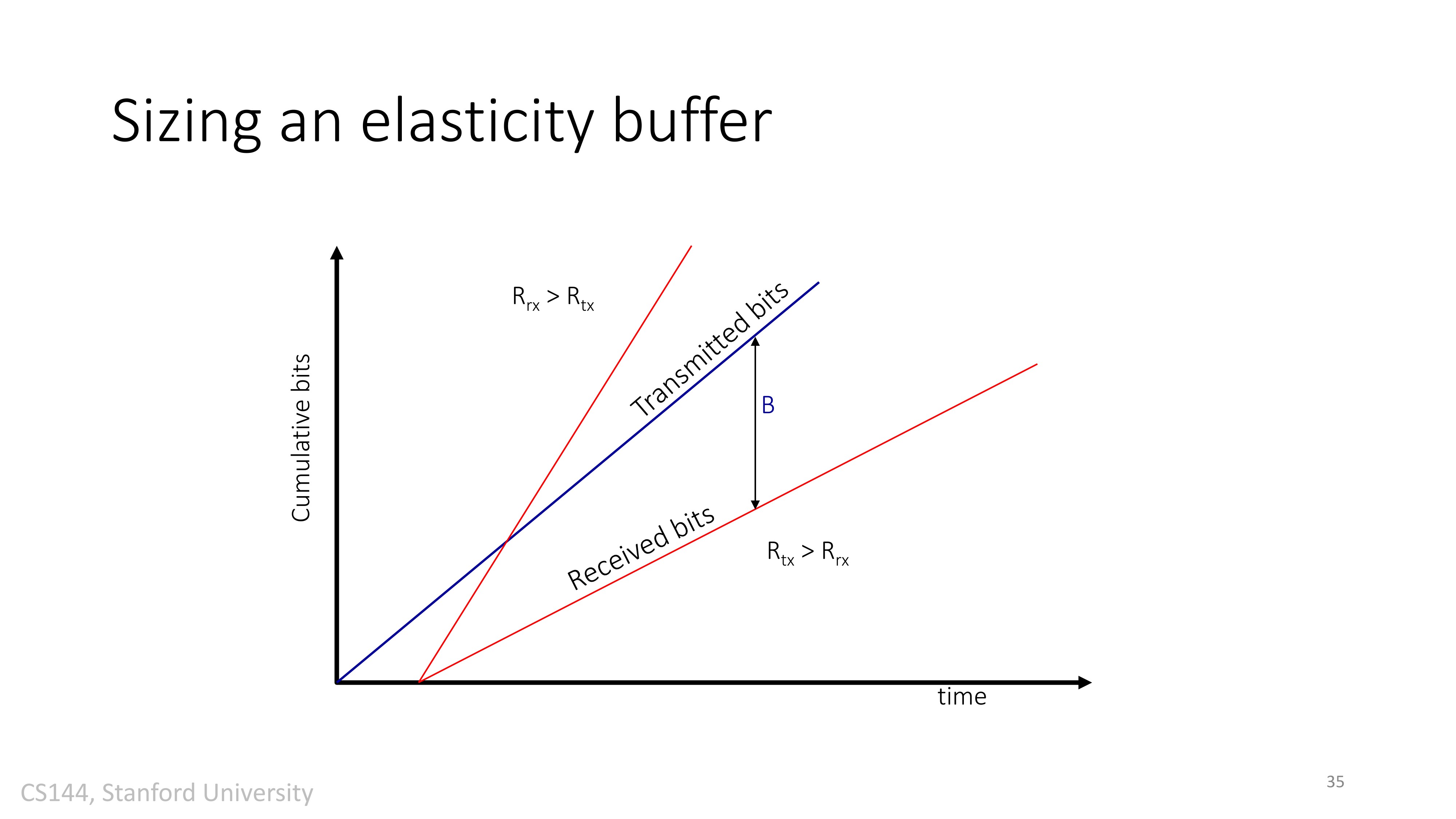
弹性缓冲器能够补偿时钟偏差, 解决了不同时钟域下的数据传输问题。结合PCIe 2.0协议, 采用常半满方式对弹性缓冲器进行了设计。
前面在介绍PCIe物理层逻辑子层的文章中,有提到过弹性缓存(Elastic Buffer,又称为CTC Buffer或者Synchronization Buffer)。其本质上是一种FIFO,主要用于解决跨时钟域问题。当然,PCIe的弹性缓存还用于补偿时钟误差(Compensate for the clock differences)。实际上,除了PCIe,弹性缓存还广泛应用于其它的高速串行接口——USB、InfiniBand、Fibre Channel、Gigabit Ethernet等基于SerDes的应用。
由于PCIe采用的基于8b/10b的嵌入式源同步时钟,接收端存在两个时钟域:一个是通过CDR从数据流中解析出来的时钟,用该时钟对数据进行采样;另一个是本地时钟域,用于其他的逻辑的。借助弹性缓存(FIFO),可以实现数据在这两个时钟域的转换。
以PCIe Gen1为例,链路上的数据速率为2.5Gbps。但实际上,任何晶振(或者其他频率发生器)都是有误差的,PCIe Spec允许的误差范围为±300ppm(Parts Per Million)。即,链路上实际的频率范围为2.49925GHz~2.50075GHz。借助弹性缓存,通过删除或者插入SKP Ordered Set可以消除链路频率误差的影响。如下图所示:
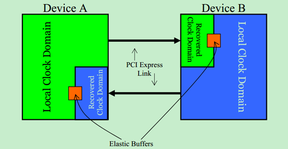
需要注意的是PCIe Spec并没有规定弹性缓存的具体位置,设计者可以将弹性缓存放在8b/10b解码器之前,也可以把弹性缓存放在8b/10b解码器之后。不过,Mindshare的建议是将弹性缓存放置于8b/10b解码器之前的。
当本地时钟域的时钟(Local Clock)的速度比数据流通过CDR解析出的时钟(Recovered Clock)的时钟要快时,且弹性缓存即将被读空之前,可以向SKP Ordered Set中插入1~2个SKP。如下图所示:

当本地时钟域的时钟(Local Clock)的速度比数据流通过CDR解析出的时钟(Recovered Clock)的时钟要慢时,且弹性缓存即将溢出之前,可以从SKP Ordered Set中移除1~2个SKP。如下图所示:
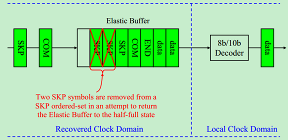
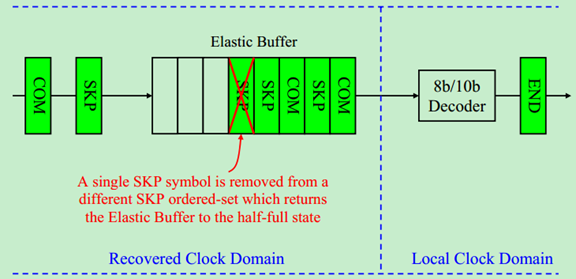
需要特别注意的是,Intel提出的PIPE规范(并非PCI-SIG强制的规范,具体参考前面关于PIPE的文章)中,只允许每次从一个SKP Ordered Set中插入或者移除一个SKP。如果需要插入或者移除两个SKP,则需要对两个SKP Ordered Set进行操作。如下图所示:
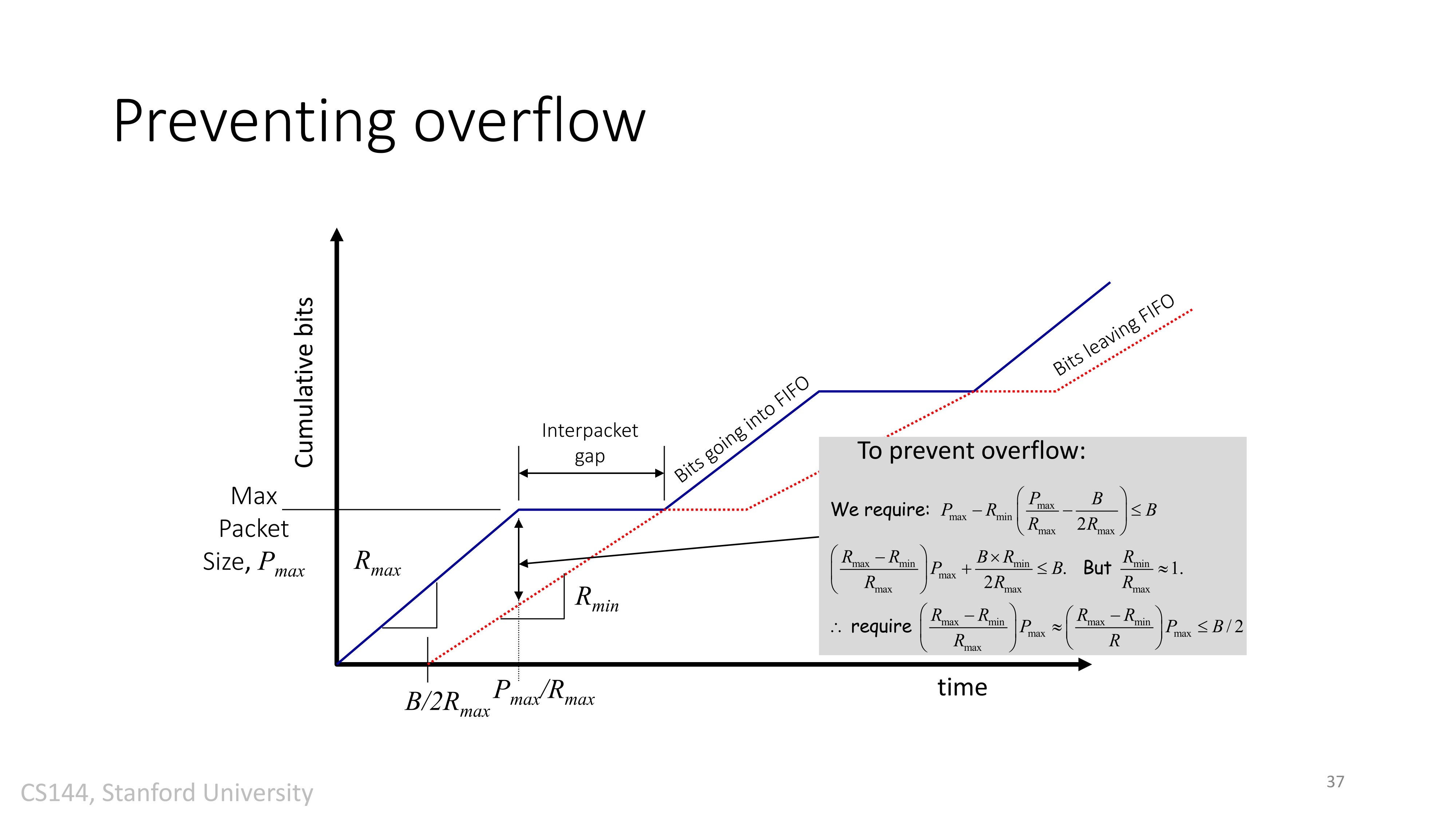
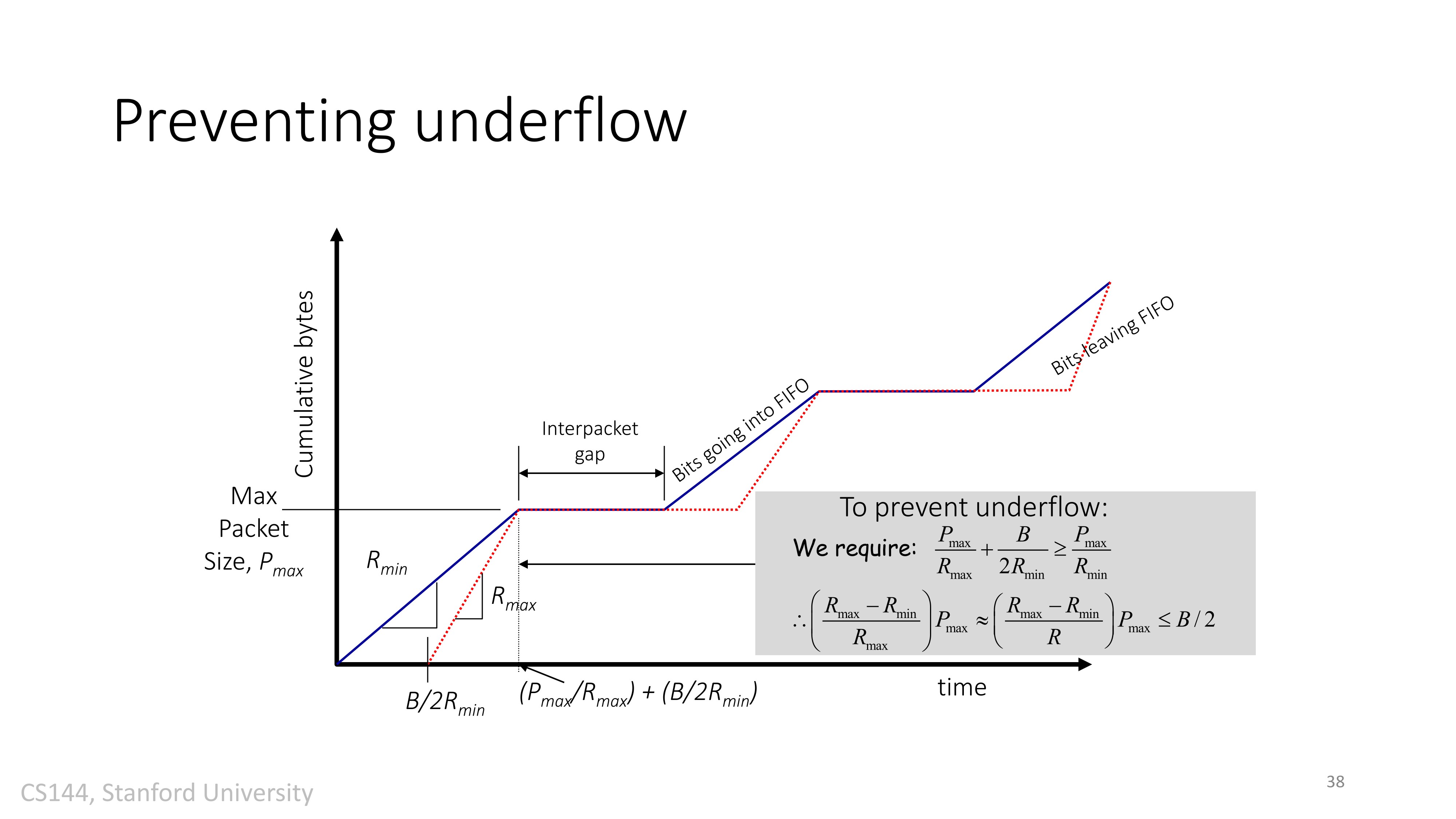
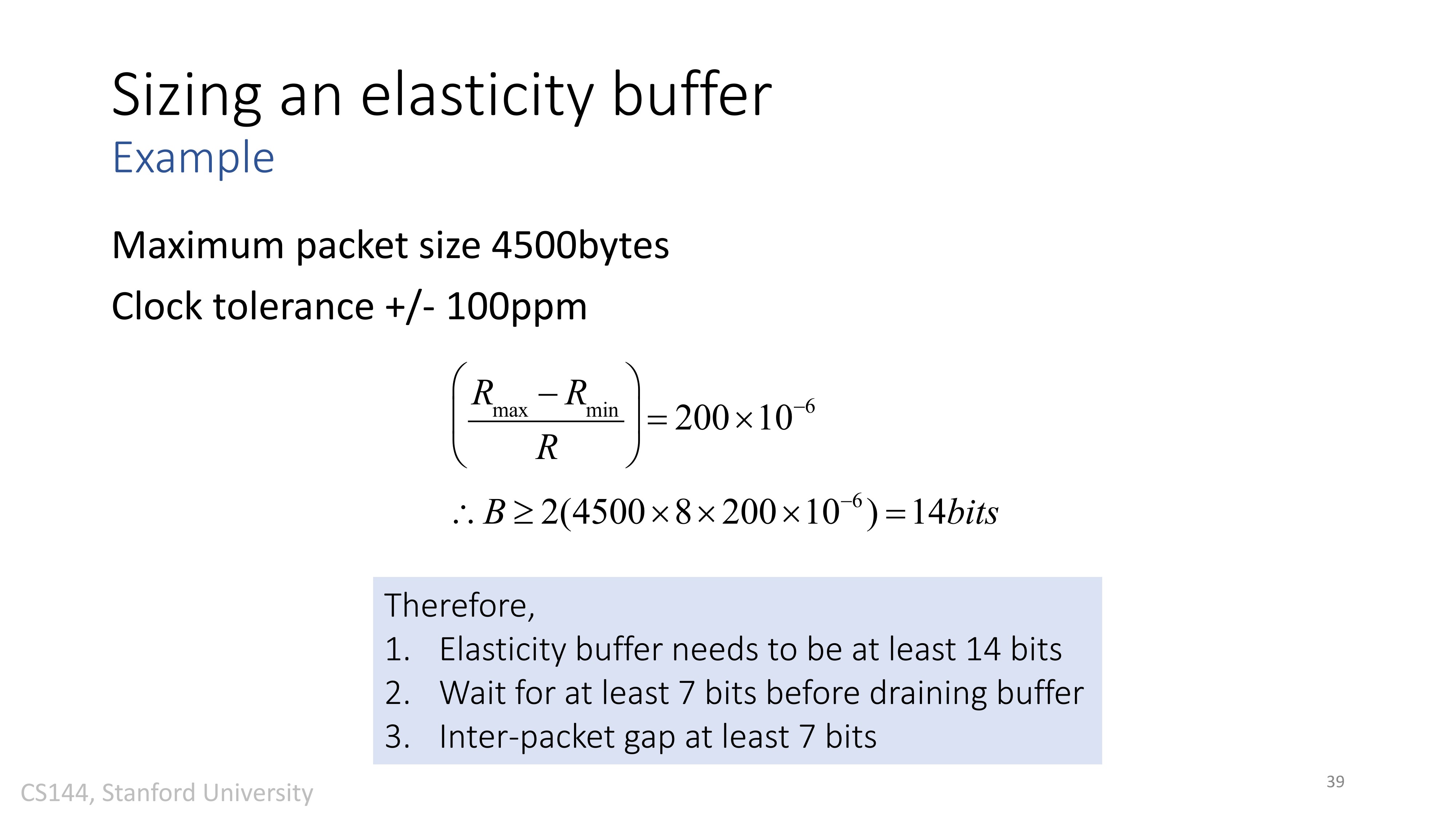
注释:
- +/- 100ppm 即 [公式]
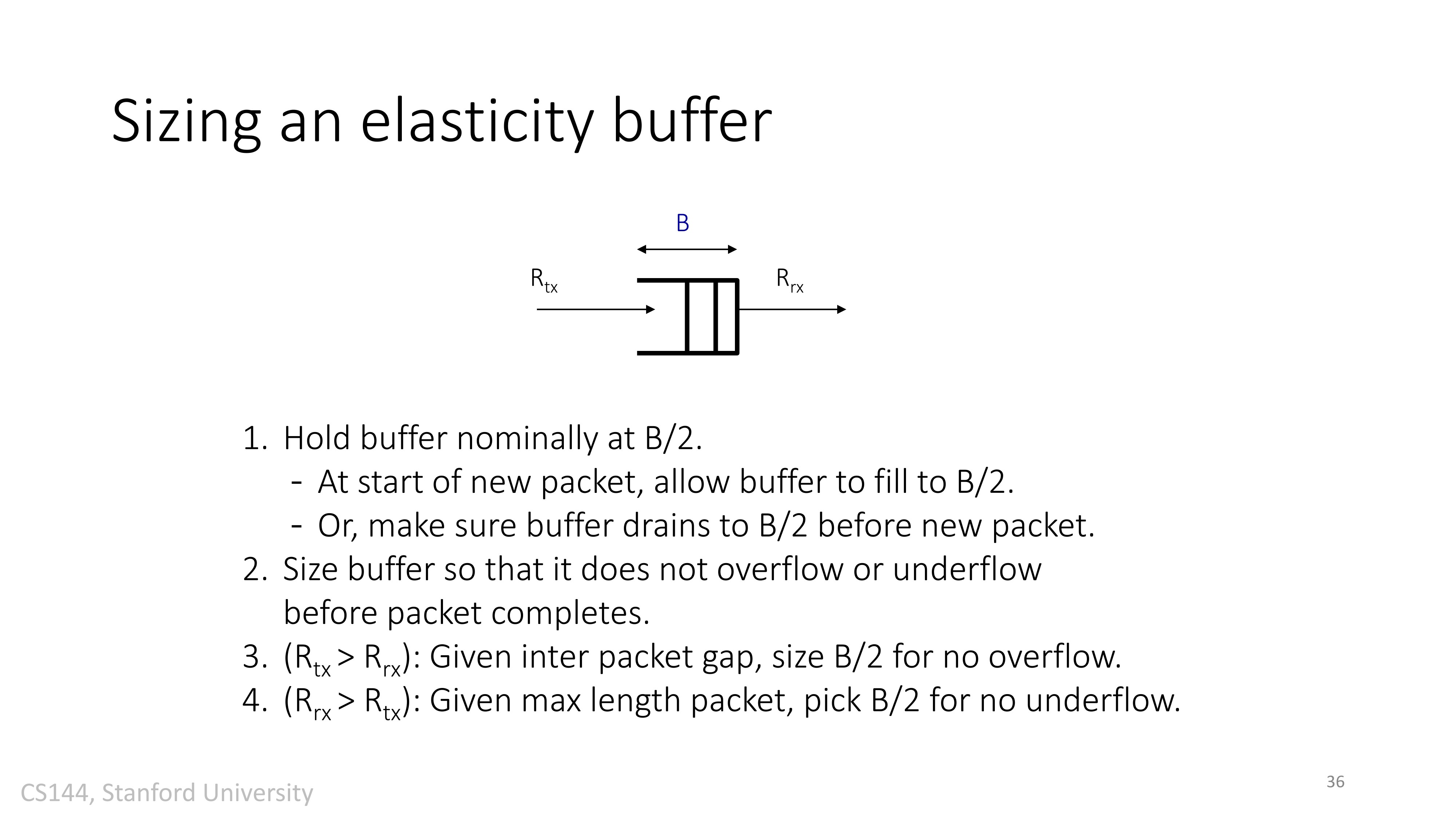
- 要等到Buffer中有一半数据之后,才开始取数据。